Bandwidth of Resonant Circuits
An important property of a resonant circuit is its bandwidth. Bandwidth is defined as the size of frequency range that is passed or rejected by the tuned circuit. To help understand bandwidth further let’s think about a radio. When you turn on a radio and you try to select a radio station, what you're doing is using the bandwidth characteristics of a tuning circuit in the radio to select your particular station. Another name for the tuning circuit is a resonant circuit. A resonant circuit has a specific frequency and bandwidth and we put that to use in the radio receiver.
Resonance can be obtained in either series or parallel circuits containing three electrical characteristics namely; resistance, inductance and capacitance. The resonant circuit below consists of a resistor, an inductor and a capacitor in series with a current meter and a voltage source. The voltage source represented by an AC symbol, is also variable in frequency. Most commonly, we use one particular AC voltage: 120 volts 60 Hz, but in this case we're very interested in the frequency being variable so it would be some value other than 60 Hz.
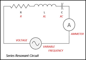
The current in the circuit can be measured with a meter or, we could calculate the current using a form of Ohm's law, which is – current (I) equals the applied voltage (E) divided by impedance or total opposition in the circuit (Z), i.e. Current = Voltage/Impedance, I = E/Z. A series-resonant circuit offers low impedance to the flow of current at a particular frequency. The circuit is said to be resonant when the frequency of the applied voltage is adjusted to produce maximum current while the magnitude of the voltage is held constant. The frequency of this voltage and current is called the resonant frequency, and is defined as the frequency at which a given system or object will respond with maximum amplitude.
Impedance
In the series RLC network the impedance is defined by the equation: 
This takes into account the opposition of the resistor (resistance R), the opposition of the inductor (inductive reactance or XL), and the opposition of the capacitor (capacitive reactance or XC). As shown in the graph below, the impedance of an AC circuit varies with frequency. Inductive reactance is directly proportional to frequency, if the frequency being applied to the circuit is increased there would be an increase in XL. Capacitive reactance on the other hand is inversely proportional to frequency so, as the frequency increases the value of XC decreases. The relationship between frequency and reactance are expressed by the equations:


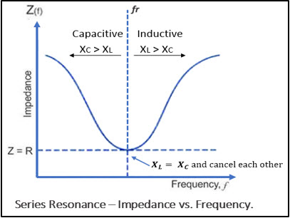
At the lower frequency most of the opposition is XC or capacitive reactance and at the higher frequencies the opposition is mainly XL or inductive reactance. At resonant frequency (fr) the inductive and capacitive reactances cancel each other out, leaving only the resistance to oppose the flow of current. When the circuit has equal values of inductive reactance and capacitive reactance, it tends to reject signals having frequencies removed from the resonant frequency. In other words, it will reject signals that are either above or below the frequency that produces resonance. Therefore, in resonant circuits, certain signals are selected to pass through while others are rejected, or blocked and this signal is referred to as a bandwidth of frequencies.
Bandwidth
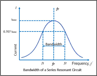
The response curve for current versus frequency below shows that current is at a maximum or 100% at resonant frequency (fr). The bandwidth (BW) of a resonant circuit is defined as the total number of cycles below and above the resonant frequency for which the current is equal to or greater than 70.7% of its resonant value. The two frequencies in the curve that are at 0.707 of the maximum current are called band, or half-power frequencies. These frequencies are identified on the curve as f1 and f2, and are often referred to as the critical frequencies, or cutoff frequencies, of a resonant circuit.
The resonant frequency can be determined from the critical frequencies by the following equation:
 or
or 
Bandwidth can be expressed mathematically as:

Other formula used to calculate bandwidth is: , where the Q factor is a measure of the quality of a resonance circuit represented by the letter Q. Q factor is calculated using the formula:

Think back to the radio example, when we are tuning in to a radio station what we're doing is adjusting the resonant frequency of a circuit to match the frequency of the carrier signal from the radio station. At the same time, we're matching the bandwidth to the music and audio that is riding on the carrier signal from the radio station.
We hope this has been helpful to you as a Technician or a student entering the field. If you have any questions about the Electronics or the Electromechanical Technician programs you can reach one of our Program Consultants toll-free at 1-888-553-5333 or by email at info@gbctechtraining.com.
Comments
Timothy, our Support Team is…
Submitted by Iris on Tue, 05/11/2021 - 09:25
Timothy, our Support Team is available to help all Electronics Technician students by phone, toll-free at 1-866-279-1457 or email support@gbctechtraining.com.
The Support Center is open for extended hours on Monday to Friday, 9 am - 10 pm in the evening and on Saturdays & Sundays from 9 am - 5 pm (EST).
The formula is valid for…
Submitted by Anonymous (not verified) on Tue, 04/26/2022 - 02:18
The formula is valid for both series and parallel tuned circuits, right?
This blog covers Bandwidth…
Submitted by Iris on Tue, 04/26/2022 - 13:27
This blog covers Bandwidth of Resonant Circuit and as mentioned “Resonance can be obtained in either series or parallel circuits containing three electrical characteristics namely; resistance, inductance and capacitance”, it focuses on series circuits. The formulas for calculating Bandwidth (BW) and Resonant Frequency (fr) are the same for both series and parallel circuits. When Q is greater than about 2 or 3, for a parallel resonant circuit, or less than 1/2 or 1/3 for a series circuit, certain simplifying assumptions can be made. The bandwidth can then be given in terms of resonant frequency and quality factor using the following formula: BW = fr / Q . However, the formulas for calculation of impedance (Z) and quality factor (Q)of parallel AC circuit is different from that used to calculate those values in a series circuit. In Parallel Z = L/RC and Q = R/XL
What is the bandwidth of a resonant circuit with a frequency of 28 MHz and a Q of 80?