The Difference Between Class A, B, AB and C Amplifiers
Used in audio equipment, radio, TV, and computers amplifiers are components that increase or amplify the voltage, current or power of an electrical signal. Almost all electronic circuits and systems use at least one stage of amplification. As engineers and technicians, we should be able to identify different classes of amplifiers.
In this blog, we will discuss the differences between the four classes of amplifiers: Class A, B, AB, and C. These are the more common types of amplifiers for linear designs.
Class A Amplifier
This class of amplifier provides very good signal reproduction. One of the primary reasons for this is that the Q-point (or operating point) is halfway between cut-off and saturation. This means it is biased midway through its active region providing a full 360 degrees of amplification despite its characteristic 180-degree inversion of the output signal. While beneficial to signal fidelity, this midway biased Q-point feature is the cause of one of the primary disadvantages to using a Class A amplifier. The transistor is always half-way on and current is always flowing. As a result, a Class A amplifier tends to generate a lot of heat leading to low efficiency (approximately 25%). It is used in low power devices such as radios and outdoor sound system and are more suited to small signal amplification. With the addition of a bypass capacitor, a Class A amplifier is capable of providing significant AC signal gain for low power devices.
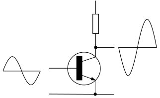
Good signal fidelity on Class A amplifier
Class B Amplifier
Unlike a Class A amplifier, a Class B amplifier does not produce a good signal reproduction. It uses complementary pairs of transistors that conducts the half cycles of the input signal. The positive biased transistor will conduct the positive signal while the other transistor is off. When the negative signal arrives, the negative biased transistor will turn on and the positive transistor turns off. Remember that transistors need approximately 0.7V to turn on and there are parts of the signal that has less than 0.7V. This alternate switching of the transistor pair causes the crossover distortion of the output signal. However, this alternate switching will generate less heat, increasing the efficiency of a Class B amplifier to 78%. This increase in efficiency makes the Class B amplifier great for battery operated devices.
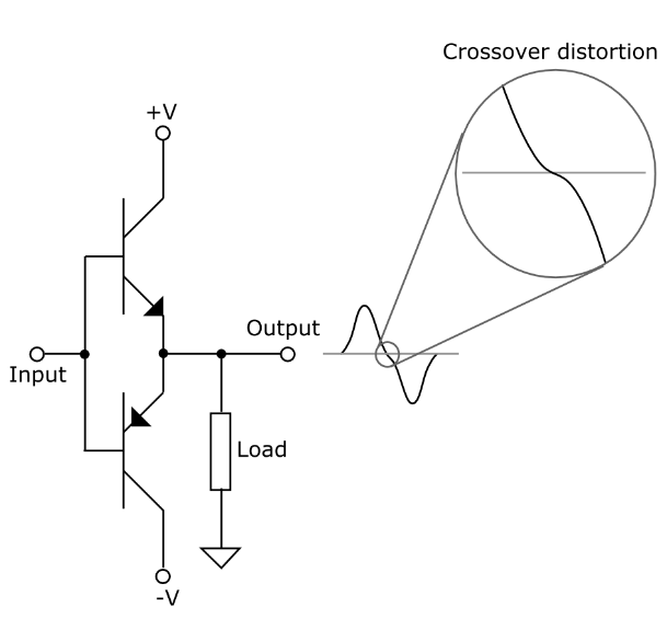
Crossover distortion on a Class B amplifier
Class AB Amplifier
The Class AB amplifier combines the strengths of Class A and Class B amplifiers. A Class AB amplifier has the good signal reproduction of a Class A amplifier and the complementary pair of transistors of a Class B amplifier which results in a better efficiency. To eliminate the crossover distortion found in a Class B amplifier, we bias the amplifier to have the complementary pair of transistors conduct at the same time. This means that both transistors conduct more than the half cycle of the input signal. Some methods of biasing voltage biasing, diode biasing, and potentiometer biasing, all present their own advantages and disadvantages. The Class AB amplifier is used in high-fidelity audio systems due to the good signal reproduction and efficiency.
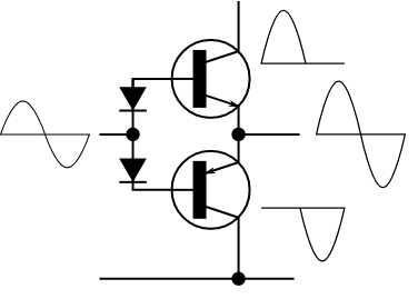
Crossover distortion eliminated on Class AB Amplifier
Class C Amplifier
Compared to the three amplifiers above, the Class C amplifier provides the best efficiency, with a rating of approximately 80%. The output signal is highly distorted since the transistor is heavily biased and is only turned on less than half of the input cycle. Since it only conducts less than half of the input cycle, it will have less heat production and therefore better efficiency than the other amplifiers. Because of the output pulse it produces, a Class C amplifier is not suitable for audio applications, rather it is ideal for radio frequency oscillators.
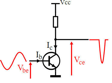
Class C Amplifier outputs less than half of the input cycle
In conclusion, amplifier classes have different characteristics and applications. There are two major characteristics that define each class: its efficiency and signal reproduction. Based on these characteristics, electronics professionals can use these amplifiers in different scenarios like single or dual polarity power supply, and application. The goal for us is to have the balance of efficiency, signal fidelity and cost in our products.
We hope that this has been helpful as a student or practicing Electronics technician. If you have any questions regarding the Electronics Technician program, feel free to get in touch with us at info@gbctechtraining.com or give us a call at 1-888-553-5333 to speak with a Program Consultant.
Comments
Though this blog only…
Submitted by Iris on Mon, 01/24/2022 - 09:53
Though this blog only focused on Classes A, B, AB and C amplifiers this response provides a comparison of Class C to class D amplifiers. Class C amplifier has the best efficiency of the four discussed and the poorest linearity with a highly distorted output wave that conducts for less than 180°. This make Class C amplifiers primarily suitable for high power, high-frequency applications, such as radio-frequency transmitters.
However, class D amplifiers moves away form linearity and would be considered no-linear digital switching amplifiers which uses pulse width modulation (PWM) technique to obtain efficiencies greater than 90% in comparison to 80% for class C or 50% for analog, they are widely used for every amplification requirement from cellphone speakers to high-end stereos. Class D amplifiers are suited for audio applications and are several orders of magnitude more efficient than traditional linear amplifiers. The high power efficiency of Class D amplifiers translates into less power consumption for a given output power but, more importantly, it reduces heatsink requirements drastically. The loading on the power transformer is also reduced by a substantial amount, allowing the use of a smaller transformer for the same power output. A drawback of Class D amplifiers concerns the challenging task of suppressing radiated and conducted interference from the switching circuitry.
Somewhat misleading characterisation of class B
Submitted by David (not verified) on Sat, 04/09/2022 - 09:59
The theoretical treatment of class B amplifiers tends to be hugely misleading since they gloss over the fact that in solid-state amps they are (at least for audio purposes) always employed with negative voltage feedback in order to work on the frequency-varying impedances of speakers as voltage sources. So the crossover distortion effects are limited to the time the output of the comparison circuit takes for transitioning the complementary driver transistor bases across the voltage range where none of them are conducting, determined by the available current, the base capacitances, and the voltage gap size.
Class B amplifiers are known…
Submitted by Iris on Tue, 04/12/2022 - 13:41
Class B amplifiers are known for their inefficient utilization of the input signal and high output distortion. However, most amplifiers (including Class B amplifiers) do use a considerable amount of feedback to reduce the distortion at the output of the amplifier. This article's discussion only covers the common differences of the various classes of amplifiers, but a more in-depth review of the various classes of amplifiers would highlight the advantages and disadvantages of each class that may reflect the benefit of each class and methods used to improve the efficiency of each class or combined classes. We will try to address this in a future blog.
It seems to me then,that a class C amplifier, switched with a pulse width or pulse position signal is incorrectly classed as a D class amp,?