The Importance of Power Factor Correction and How It Can Be Accomplished
In this installment of The Practicing Technicians Series we will be discussing the significance of power factor correction. As a technician, you may be responsible for monitoring and adjusting the power factor of your industrial operation. Many industrial applications involve induction motors or other equipment that results in supply voltage and supply current being out of phase. This is wasteful and expensive for power providers. In light of this fact, power companies will offer financial incentives by way of reduced rates to those customers who maintain a power factor as close to 1 as possible. Often, technicians will be charged with monitoring and/or correcting this “out of phase” relationship between supply voltage and current. It can be demonstrated that you can obtain the same real power dissipation (in Watts) with less current required if you maintain a power factor as close to 1 as possible. When voltage and current are in phase, the load appears purely resistive to the source and volt-amperes or VA are kept to a minimum. True power (Watts) has no VA component unlike apparent power. Power factor correction aims to bring the apparent power value (measured in VARs or volt-amp-reactive) as close as possible to the amount of true power you are using in Watts. This will result in less current being needed to provide the same amount of true power. Changes in plant equipment can often result in the need for power factor correction in order to maintain the benefits of in phase voltage and current and the resulting reduction to power costs.
We will work through an example of power factor correction by assessing the phase relationship of the supply voltage to the supply current. We will be calculating the amount of capacitance we need to add to our inductive load in order to bring the power factor back to 1. With all inductive loads, voltage is leading current and in order to bring these two parameters back into phase, we need to add some capacitive reactance to the circuit to offset the phase imbalance.
How do we calculate power factor?
Power Factor can be calculated by taking the cosine of the phase angle between the supplied voltage and the supplied current.
Power Factor = cos (theta)
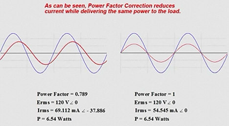
Voltage and Current out of phase Voltage and current in phase

When the voltage and current are in phase, the angle is equal to zero. The cosine of zero equals 1. Any difference between the phase of the voltage, and the phase of the current results in a non-zero phase angle resulting in a power factor of less than 1 as the cosine of any angle other than 0/360 will range from 0 to less than 1.
A second relationship describes this quantity (power factor) as the ratio of True Power in Watts, to Apparent Power in VA (volt-amperes)
Power Factor = True Power / Apparent Power
How do we resolve any existing phase difference?
When the load is predominantly inductive in nature, in order to acquire a power factor of 1, we most often will introduce the correct amount of capacitive reactance to the load in order to bring supply voltage and supply current back into phase. This is accomplished by measuring the phase difference between the voltage and the current, and then using that value to calculate the inductive reactance in the load. Once you know that, you only need to calculate the required parallel capacitor value needed to make the load appear completely resistive to the source. Set XC = XL.
Step 1: Calculate Z (total impedance)
Z = Erms / Irms
Step 2: Measure the phase angle (theta) between voltage and current
Theta (this example) = -37.8 degrees
Step 3: Calculate XL
XL = Z sin (theta)
Step 4: Use XL and supply frequency to calculate required capacitor value
We know that for the load to appear resistive, XL = XC
XC = XL
XL = 1 / 2*Pi*f*C
C = 1 / 2*Pi*f*XL
Step 5: Place a capacitor of the value calculated in step 4 in parallel with the load. This will cause the load to appear purely resistive as the inductive and capacitive inductances cancel each other out and the voltage and current from the source will now be in phase.
In practical terms, this procedure results in less current being required to provide the same real power to the load. This results in reduced operating costs for your industrial application by way of cheaper power rates from your utility company.
In the video animation provided below, We walk through an illustration of how current demand is reduced while providing the same real power in Watts to the plant floor.
If you liked this post, check out our previous articles in The Practicing Technician’s Series;
Using the Natural Log or “ln” Function in Circuit Analysis
How to Create Correct Ohm's Law KCL Branch Equations for Nodal Analysis
How to Solve Simultaneous Equations with Multiple Unknowns
Converting Parallel RL Circuits to their “Easier To Work With” Series Equivalents
Common Rules For Weighted Number Systems
The Utility of Finding the Thevenin Equivalent Circuit
The Significance Of Conductor Resistance And How To Calculate It
We hope this has been helpful to you as a practicing or student technician. We are looking for other ideas for this continuing Practicing Technician series. Please let us know what you would like us to write about by sending us your thoughts and questions at support@gbctechtraining.com.