How to Create Correct Ohm’s Law KCL Branch Equations for Nodal Analysis
In our second installment of the series we take a look at Nodal Analysis for technicians. Nodal analysis is a means of determining the voltage present at a node of interest with respect to a specified reference point. Many technicians have difficulties creating valid Ohm’s Law representations for the KCL (Kirchhoff’s Current Law) node equations when trying to perform this type of circuit analysis. They often struggle with the concept that arbitrary branch current directions can be assigned at the start of the analysis, and the correct results can always be arrived at regardless of whether or not the branch current actually flows in the assumed direction.
The key to this analysis is to ensure that you state your current law equations for each node of interest in terms of your selected current direction. This sounds simple, however, this is the stage at which most errors occur when performing this type of analysis. Below, I provide a straight forward approach that will always yield correct current law equations for independent nodes in any linear DC network. The most important thing to consider is how to define the unknown current which flows between the node of interest and the reference node. If this representation of branch current is incorrect, the entire analysis will be invalid. The correct application of Ohm’s law in terms of the assumed current direction is essential to identifying node voltages and their polarities with respect to the specified reference node when performing this type of analysis. Below are the six scenarios that can exist when creating equations used to describe branch current flowing into or out of an independent node. Every branch in the linear DC network can be reduced to one of these six scenarios.
In Figure 1-1a, a known resistance is connected between two nodes in a network. We desire an equation that will define the current flowing through the resistor, in terms of the voltages present at the two nodes and the displayed direction of current flow. This current will allow us to define the voltage at node A.
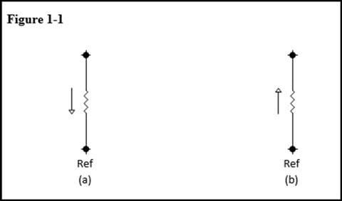
When current is flowing from node A towards the reference node as in Figure 1-1a, according to electron flow, node A must be at a lower voltage than the reference node. A current flowing in the direction shown can be expressed using Ohm’s law as follows:
When current is flowing from the reference node towards node A as in Figure 1-1b, the reference node is at a lower voltage than node A. A current flowing in this direction can be expressed using Ohm’s law as follows:
In Figure 1-2a, a voltage source appears between the node of interest and the reference node, its effect on the current flowing through the resistor must be taken into account. When examining the effect of the voltage source, you need to determine if the polarity of the voltage source adds to the current in the assumed direction, or does it oppose it. Electrons flow out of the negative terminal and into the positive terminal of a voltage source. If the direction of flow for the source agrees with the direction of flow that was assumed, the source would be adding ( Vs / R ) to the current already flowing between the nodes prior to the sources introduction. (See above)
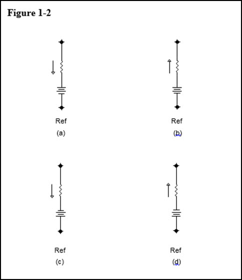
The expression for the current flowing in Figure 1-2a is similar to that in Figure 1-1a except that the effect of the voltage source on the current flowing through the resistor needs to be included in the expression. An easy way to visually determine the sign to use when accounting for the effects of the source (to add it or subtract it) is to apply the sign of the source terminal into which the current flows. In this example, the current flows into the positive terminal of the voltage source. This agrees with the assigned current direction and the current from the voltage source is therefore added to the expression for the current.
The expression for Figure 1-2b is based on that in Figure 1-1b. Once again, the effect of a voltage source needs to be accounted for in the node voltage expression. This time, since the current enters the negative terminal of the voltage source, its contribution is subtracted from the expression for the current.
Figure 1-2c is basically the same as Figure 1-2a except that the voltage source is connected in the opposite direction. This means that the current is entering the negative terminal of the source and you must subtract its contribution from the expression for the current between the two nodes.
Figure 1-2d is similar to Figure 1-2b but once again the voltage source is connected in the opposite direction. The current shown to be flowing, enters the positive terminal of the voltage source indicating that the contribution from the voltage source should be added.
The previous equations, labelled 1 through 6, are essential to the proper application of nodal analysis to linear (resistive) DC networks. Any number of resistances and/or voltage sources between the node of interest and the reference node can be reduced to one of the six configurations illustrated in the above examples.
Using Nodal Analysis to Solve Linear DC Networks
There are eight basic steps to follow when performing a Nodal Analysis on a linear DC network. With the aid of the six equations provided above, the steps outlined below will ensure that you arrive at the correct values when performing the analysis.
Step 1: Identify all nodes in the circuit.
Step 2: Select a reference node.
Step 3: Identify the independent nodes in the circuit. An independent node is a node whose voltage is determined by the size of the resistor and circuit configuration. Assign an arbitrary current direction for all currents entering or leaving the independent nodes in the network.
Step 4: Write the KCL equation for the currents entering or leaving each independent node in terms of the chosen current directions.
Step 5: Use Ohm’s law to express each current listed in the KCL equations for the independent nodes keeping the assumed current direction in mind. Use the appropriate equation from the 6 equations outlined above paying close attention to the chosen direction of current flow.
Step 6: Express the KCL equations for the independent nodes using the Ohm’s law representation obtained from step 5.
Step 7: Solve for the independent node voltages using the equations obtained from step 6. (Use the same approach outlined for Loop analysis when solving the multiple simultaneous equations.)
Step 8: Use the acquired node voltages with the Ohm’s Law representations for branch current, to solve for the unknown independent node currents. A positive current value result means that the current flows in the direction arbitrarily chosen at the start of the analysis. If the branch current value is negative, it means that the current actually flows in the opposite direction than the assumed one.
In the video animation below, I provide a step by step solution to a sample Nodal Analysis problem. Each step in the solution is illustrated here for those who wish to see an example of this approach being used.
We hope this has been helpful to you as a practicing or student technician. If you liked this post check out our previous article in The Practicing Technician Series; Using the Natural Log or “ln” function in circuit analysis.
We are looking for other content ideas for this continuing Practicing Technician series. Please let us know what you would like us to write about by sending us your thoughts and questions to support@gbctechtraining.com.