How to Perform Loop or Mesh Analysis on a Linear DC Network Using Kirchhoff’s Voltage Law
Loop current analysis or mesh analysis is an analytical method to determine the current flowing at different points in a closed circuit. Kirchhoff’s voltage law and Ohm’s law are used to calculate the current flowing through each resistor and their corresponding voltage drops, when performing loop analysis in a circuit.
There are six general steps are required to perform a loop or mesh circuit analysis on a resistive DC network.
- Identify and assign arbitrarily a direction to the loop currents in the circuit.
- Mark the polarity of the elements in each loop in terms of our assumed current direction.
- Create the Kirchhoff’s Voltage Law (KVL) equation for each loop in terms of the specified loop direction.
- Use Ohm's law. to specify the unknown KVL voltages in each loop equation in terms of current and resistance.
- Calculate the KVL voltage expressions for each loop in the circuit, use substitution and elimination to solve for the unknown loop currents.
- Use the loop currents to calculate resistor current and voltage throughout the circuit.
Identify and assign a direction to the loop currents
To analyze the above circuit, we will begin by identifying and assigning a direction to the loop
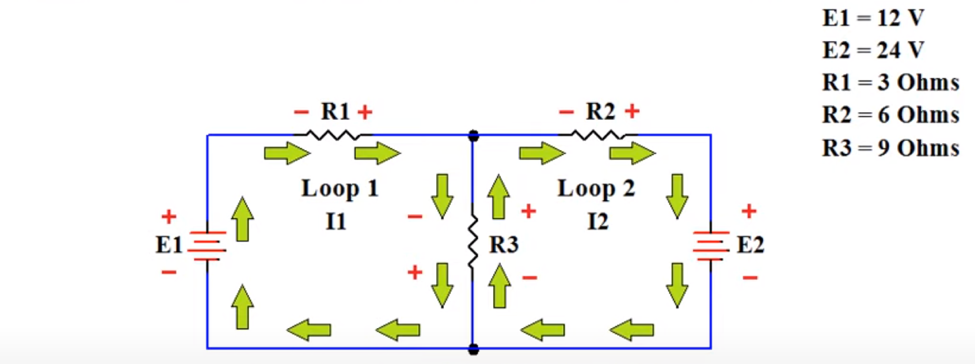
currents in the circuit. The first loop current I1 flows through resistor R1, resistor R3 and voltage source E1. We have chosen arbitrarily a clockwise direction to represent the current flowing around Loop 1 in the circuit. The second loop current I2 flows through resistor R2, voltage source E2, and resistor R3. As with loop one, we have also assigned clockwise current for the second loop.
Mark the polarity of the elements
Next, we will mark the polarity of the elements for each loop in terms of the assumed current direction that we have already assigned. Starting with loop 1, we will mark the known polarity of the voltage source E1. According to the electron flow, we know that current enter to the negative end of the element and exit through the positive end. We can assign polarity to the remaining element of the loop 1 according to that. For loop 2, first we will mark the known polarity of the voltage source E2 and then assign polarity of the remaining elements according to the electron flow.
Create the KVL equation for each loop
In the third step of the process, we will be constructing Kirchhoff’s voltage law equation for each loop in the circuit. We will start from the upper left-hand corner of loop 1 and travel around the loop in a clockwise direction. When you travel from the negative end of an element to the positive end of an element, the voltage is considered positive and is added when constructing the KVL expression. On the other hand, if you travel from the positive end of an element to the negative end of an element, the voltage is subtracted in the KVL equation. Considering the voltage across the resistor R1, we're moving from negative to positive. This means that this value is added or positive. For the voltage across resistor R3, we are once again moving from negative to positive, so this voltage is added as well. We complete our walk around the loop by considering the voltage on E1. This voltage also is added as we're moving from negative to positive. Kirchhoff's voltage law states that the algebraic sum of the voltages around any given loop must equal zero. We therefore set this new equation equal to zero for loop 1.
VR1 + VR3 + E1 = 0
Now we will construct the KVL equation for loop 2 in same way. Starting in the upper left corner of loop 2, we once again move in a clockwise direction around the loop. For voltage across the resistor R2, we're moving from negative to positive, so the value is added or considered to be positive. When we come to the E2 voltage source, we're moving from positive to negative polarity, therefore, the value of E2 is subtracted in the KVL equation. For voltage across the resistor R3, we're moving from negative to positive, so the value is added, and the entire equation is set to equal zero for loop 2.
VR2 – E2 + VR3 = 0
Use Ohm's law to specify the unknown KVL voltages
Next, we will be using Ohm's law to re-express the voltage drops in each of the loop equations. Beginning with loop 1, the R1 voltage drop can be restated as the value of R1 times current I1. When expressing the voltage drop across R3 in this manner, it's important to note that the current for R3 is a combination of I1 and I2. As we have expressed the I1 and I2 currents as moving in opposite directions, the value of the voltage drop across R3 for loop 1 will be the value of R3 times the I1 current less the I2 current. For loop1,
R1*I1 + R3*(I1 – I2) + E1 = 0
When we deal with loop 2, this R3 current value will be expressed as (I2 – I1). Now we will substitute the known resistance and sources values into the modified KVL equation of loop 1. Next, we will expand the equation and then collect like terms to state the equation with unknowns on one side and a known voltage on the other.
Here the values that have already given, E1 = 12 V, E2 = 24 V, R1 = 3 Ohm, R2 = 6 Ohm, R3 = 9 Ohm. So, substituting these values in loop 1 equation we get,
3*I1 + 9*(I1 – I2) + 12 = 0
3I1 + 9I1 – 9I2 + 12 = 0
12I1 – 9I2 = -12
We will repeat the process for loop 2 to obtain the Ohms law representation of the loop 2 KVL equation Notice that as we will be working with loop 2, the I1 current will be subtracted from the I2 reference current when we will be considering the voltage drop across R3. Then we will substitute in our known values, expand the equation, collect like terms, and separate those terms with unknown quantities from those of constant value voltages. Now that we have 2 KVL equations with 2 unknowns, I1 and I2.
R2*I2 – E2 + R3*(I2 – I1) = 0
6*I2 – 24 + 9*(I2 – I1) = 0
6I2 – 24 + 9I2 – 9I1 = 0
-9I1 + 15I2 = 24
Calculate unknown currents using KVL voltage expressions for each loop in the circuit
Now we will solve these unknown values. To get the value of current I1, we will eliminate the I2 terms from these equations. To do this we will find the lowest common multiple for the I2 coefficients. In this case will be 45. This is accomplished by multiplying the loop 1 equation by 5, and by multiplying the loop 2 equation by 3. Depending on the sign of the I2 coefficients, we either add or subtract these two new equations from each other to eliminate the I2 term and solve for I1
60I1 – 45I2 = -60
-27I1 + 45I2 = 72
Since the coefficients for I2 do not have the same sign, we will therefore add the equations and it will result in zero I2. Once the I2 term will be eliminated, we will proceed by solving for I1.
60I1 – 45I2 = - 60
33I1 + 0I2 = 12
I1 = 12/33
I1 = 0.363636 A
I1 = 363.636 mA
After obtaining the value of the I1 loop current, we will use substitution to obtain the I2 loop current. Using the loop 1 equation, we will substitute in the value for I1 and proceeded to calculate the value of I2. Using loop 1,
12(0.363636) – 9I2 = -12
4.363632 – 9I2 = -12
-9I2 = -12 – 4.363632
I2 = -16.363632/-9
I2 = 1.81818 A
To confirm the validity of our calculation, we could also substitute the I1 value into the loop 2 equation and we should end up at the exact same result. Using loop2,
-9(0.363636) +15I2 = 24
-3.2727 + 15I2 = 24
15I2 = 27.272724
I2 = 27.272724/15
I2 = 1.81818A
It is also important to note that instead of solving for I1 by eliminating I2 as we did at the start step 5, we could just as easily have solved for I2 by eliminating I1.
Having determined the value of I1 and I2, it is easy to calculate the value of IR3, and move on to the final step of the process. Because the loop 2 and loop 1 currents flowing through resistor R3 are flowing in opposite directions and the loop 2 current is larger, the net resulting current, I3 will flow in the same direction as loop current I2.
I3 = I2 – I1
I3 = 1.818 – 0.363636
I3 = 1.454 A
Use the loop currents to calculate resistor current and voltage
With all three resistor currents known, it is a simple matter of applying Ohm's law to calculate the voltage drop across each resistor. The voltage drop across the resistor R1 is,
VR1 = I1 x R1
= 0.363636 x 3
= 1.091 volt
Resistor R2 is dropping,
VR2 = I2 x R2
= 1.81818 x 6
= 10.909 volt
Finally, we calculate the voltage drop across resistor R3,
VR3 = I3 x R3
= 1.454 x 9
= 13.086 volt
In this example, we tried to explain the steps of analyzing a circuit using loop current analysis or mesh analysis. Using loop analysis, we can easily calculate the voltage drop of different elements in the circuit and the amount of current flowing through them as well.
We hope that this has been helpful as a student or practicing Electronics technician. If you have any questions regarding the Electronics Technician program, feel free to get in touch with us at info@gbctechtraining.com or give us a call at 1-888-553-5333 to speak with a Program Consultant.